Quantcast
Channel: Embedded Lab » Power Supply
Viewing all 16 articles
Browse latest View live

DIY battery backup for your Raspberry Pi


DC booster for your 12V load

$
0
0

This 12V DC booster circuit uses the MC34063A device which contains all the primary functions required for DC−to−DC converters. It has a built-in temperature compensated reference, comparator, controlled duty cycle oscillator with an active current limit circuit, driver and high current output switch. It operates from 3.0 to 40.0V DC and can supply output current up to 1.5A. This booster can thus power your 12V load with a 3.7V Li-Ion battery.

DC-to-DC booster using MC34063

DC-to-DC booster using MC34063

The post DC booster for your 12V load appeared first on Embedded Lab.

Supercapacitors for reliable backup power in embedded systems

$
0
0

From Samuel Nork’s article “Supercap backup circuit provides reliable uninterrupted power

Temporary backup power is a common requirement for a wide range of applications whenever the main power source is suddenly unavailable.  Examples include data backup applications ranging from servers to solid-state drives, power fail alarms in industrial or medical applications, and a host of other “dying gasp” functions where orderly power-down must be assured and system status communicated to a powered host.  In the past, these types of high reliability systems used batteries to provide an uninterrupted power source whenever the main supply of power was inadequate or unavailable.


However, many trade-offs accompany battery backup, including long charge times, limited battery lifetime and cycle life, safety and reliability concerns, and large physical size.  With the advent of high value electric double layer capacitors, better known as supercapacitors, alternate backup architectures may be employed which eliminate many of these trade-offs.

Supercap charger and backup control circuit using

Supercap charger and backup control circuit using LT3350

dd

The post Supercapacitors for reliable backup power in embedded systems appeared first on Embedded Lab.

Switching regulators guide

TPS61230 based 5V LiPo Booster

$
0
0

Jianan Li, a ECE and CS student at Duke University, has designed this 5V LiPo Booster based on TI’s TPS61230 IC. It is breadboard-friendly and it can be directly plugged into the power rails of breadboards of multiple sizes without blocking the vertical 5-pin strips. Jianan has posted the Eagle design files and BOM on Github.

5V Lipo booster

5V Lipo booster

The post TPS61230 based 5V LiPo Booster appeared first on Embedded Lab.

STM32 powered miniature power supply

Making a low cost portable phone charger

$
0
0

If you have any spare old phones with no use lying around, you may want to use their batteries to build this portable charger for your new smartphone. On the electronics side, this project only requires a LiPo battery charger module and a step-up voltage converter module, both of which can be bought for less than $5 on eBay.

DIY portable phone charger

DIY portable phone charger

The post Making a low cost portable phone charger appeared first on Embedded Lab.

Open source, modular bench power supply

$
0
0

Here’s a neat bench power supply design from a Hackaday user which offers very interesting features such as software calibration, programmatic control via USB Raw HID, etc at an affordable price. While this is still an ongoing project, the author defines his final goals of this project as:

  • Modular power supply from 1 to 6 channels (I am planning on having 4: 3x positive, 1x negative)
  • Each channel can independently be set from 0-12V (for positive channels) or -12-0V (for negative channels), and the output can go all the way to 0.
  • Configurable set points for voltage and max current for each channel
  • Actual readings for voltage and current for each channel
  • Low cost – it’s not as cheap as scrapping an ATX power supply (which is what I am using today), but the extra features such as current limiting should more than make up the extra cost.
  • Active (fan) cooling combined with heat sinks to support sustained high current loads
  • USB control (voltage and current set points), logging of actual voltage / current readings, and computer-based calibration.
  • The ability to use potentiometers for voltage / current set points instead of a microcontroller, if desired (each channel has four analog I/Os: Voltage and Current setpoints, and Voltage and Current sense outputs. All of these are in the range of 0-5V, allowing easy control from either a potentiometer or a DAC.
Bench power supply

Bench power supply

The post Open source, modular bench power supply appeared first on Embedded Lab.


Dual channel battery charger plus analyzer

$
0
0

K.C. Lee‘s dual channel battery charger is a microcontroller-based efficient switching mode power supply design for not only the charging job but also for determining the charge/discharge characteristics of batteries.

Dual channel battery charger

Dual channel battery charger

It is a battery charger/analyzer. It is not going to save the world from an alien invasion or cure cancer or something equally noble. It is a nice tool for recycling or buying cheap batteries of unknown capacity/performance as it’ll let you test the discharge characteristics.

What set this charger design different are:

  • Flexible power source – two independent buck/boost converters allow higher/lower than input voltage. So you could be charging batteries from USB, vehicle power or green power source such as unregulated power from small solar power panel/wind power etc.

  • High switching frequency beyond traditional uC PWM type of design can offer. This allows for the use of much smaller components and also reduces input/output ripple current.

  • During discharge mode, the switch mode converter works to draw power away from the battery. The power can be diverted to external use. e.g. charging a Super capacitor bank, light. etc.

  • Scalable design for additional channels and/or higher power.


The post Dual channel battery charger plus analyzer appeared first on Embedded Lab.

Prototyping board with built-in power supply

$
0
0

This prototyping board with built-in regulated power supplies was designed by Electro-Lab and consists of four independent DC-DC buck converters based on LM2675-ADJ and generates 3.3V, 5V, 12V and -12V at 1A.

DIY prototyping board with regulated power supplies

DIY prototyping board with regulated power supplies

Prototyping is a useful and powerful method in electronics which lets us analyze a circuit before using it in a system or turning it into a product. In this process we may need a single supply or multiple supplies to power the circuit depending on the type of the application. For example, an op-amp circuit may need a symmetrical supply such as +12V and -12V or a logic circuit may require both 5V and 3.3V at the same time. Some applications may need three or more. This means we should have a bench supply with multiple outputs or multiple bench supplies in the environment. This may not be always possible. This DIY Prototyping Board is designed to provide all the most used supply voltages that a designer will need during prototyping a circuit. The switching power supplies on the board output 3.3V, 5V, 12V and -12V rated at 1A independently. In addition those there are two precise voltage references at 5V and 2.5V provided especially for op-amp based applications.

The post Prototyping board with built-in power supply appeared first on Embedded Lab.

DIY power bank using recycled Laptop battery

$
0
0

This DIY power bank project from Do It Yourself Gadgets uses recycled laptop battery and a 5V boost converter to construct an USB charger.

DIY power bank using laptop battery

DIY power bank using laptop battery

This article will show you the basic powerbank circuit consisting of Lithium cell charging circuit, boost converter and toggle switch as well as my improved version with self activating boost converter and LED status indicator and homemade housing. It all started with an old Lenovo laptop battery. I carefully pried it open to examine the cells. Three packs of two parallel 18650 Lithium 2200 mAh cells were connected in series.

The post DIY power bank using recycled Laptop battery appeared first on Embedded Lab.

A very simple DIY solar-powered USB charger

$
0
0

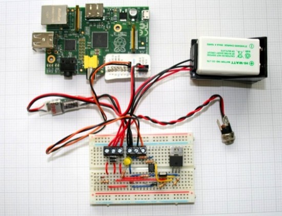
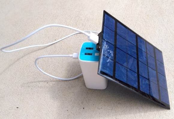
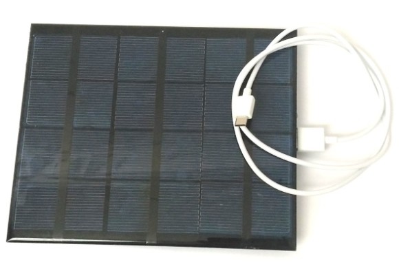
Yesterday, I built a very simple DIY solar-powered USB charger for my TP-link 10400mAh USB Power Bank. All I needed was a 6V/3.5W solar panel and the TD1410-based 5V buck converter module. I bought both of them on Aliexpress for less than $8.

charger1

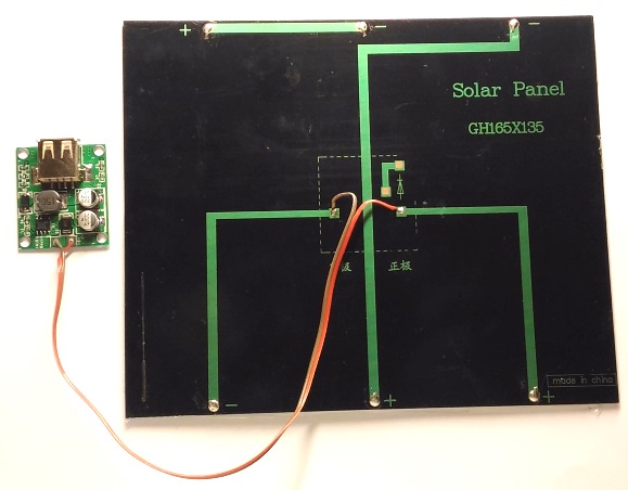
Simplest DIY solar-powered USB charger

It was one of the easiest projects I built. All I needed to do was to connect the input of the 5V step-down buck converter to the output of the solar panel using two wires.

charger3

Connections between the 5V buck converter and solar panel

From TD1410 datasheet,

The TD1410 is a 380 KHz fixed frequency monolithic step down switch mode regulator with a built in internal Power MOSFET. It achieves 2A continuous output current over a wide input supply range with excellent load and line regulation. The device includes a voltage reference, oscillation circuit, error amplifier, internal PMOS and etc.

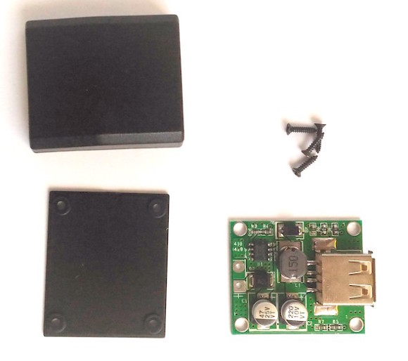
For 5V output from TD1410, the input voltage can range from 5.5V to 20V (from the datasheet). I measured the solar panel open-circuit voltage under sunny conditions to be ~ 6.5V. Under the load of 200 mA, the solar panel output voltage was reduced to ~6.0V. The TD1410-based 5V buck converter module that I purchased on Aliexpress already has a diode at its input for polarity protection. So I didn’t need any extra diode for the solar panel output as it directly goes to the input of the buck converter. The nice thing about this buck converter is it has a USB-A female port for output, which is same as found in standard USB chargers. It also comes with a plastic enclosure (see pictures below).
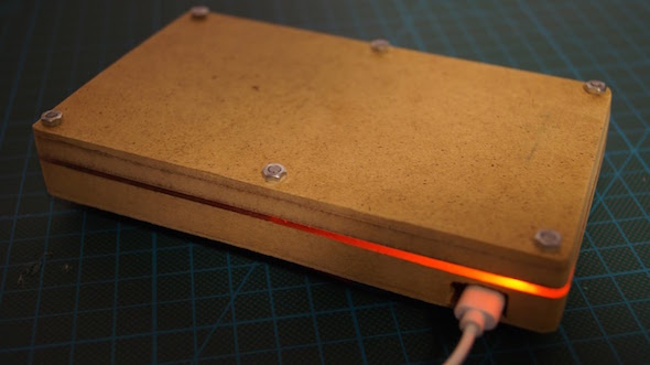
Buck converter with plastic enclosure and screws

Buck converter with a plastic enclosure and screws
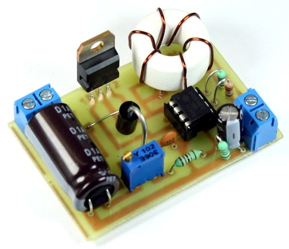
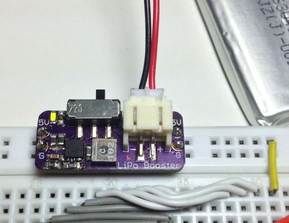
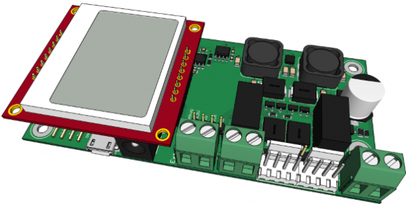
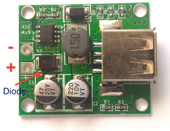
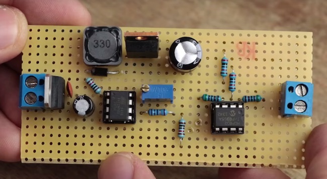
Close up view of TD1410-based 5V buck converter

Close up view of TD1410-based 5V buck converter

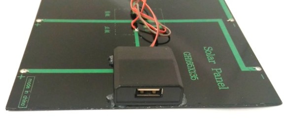
The positive and negative outputs from the solar panel connects to the + and inputs of the buck converter, respectively. I put the buck converter inside the enclosure and glued it on the back of the solar panel as shown below.

5V converter module glues to the backside of the solar panel

5V converter module glued to the backside of the solar panel

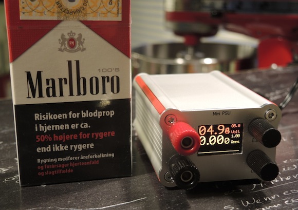
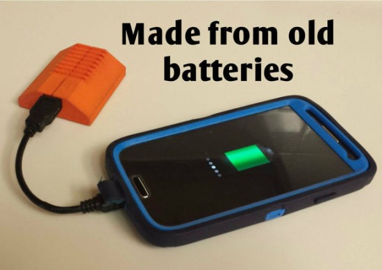
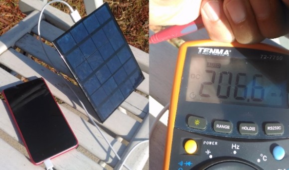
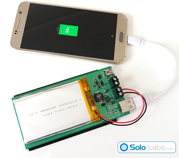
The USB output voltage from the buck converter was measured to be 5.05V using my TENMA multimeter. I could even charge a Xiaomi Redmi Note 2 smartphone directly from the USB port under full sun conditions. I measured the charging current was ~200 mA. If the sky is partly cloudy, the solar panel might not supply the adequate current for charging the smartphone directly (of course, it also depends upon the smartphone). In the absence of enough input current, the smartphone’s built-in charging circuitry will refuse to go in to the charging mode. If there’s a fluctuation in the incident solar irradiation due to varying cloud condition, it is likely that the smartphone will go back and forth between charging and not charging. So, I would not recommend it for direct charging of smartphones. But it is safe for charging the USB power banks as they can be charged at a lower current input.

charger2

Direct charging of smartphone (at 200 mA) using the solar power. Charging is interrupted under partly cloudy conditions.
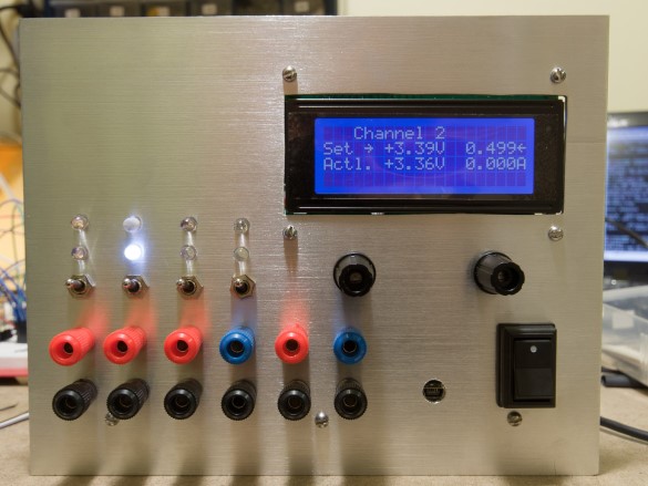
s

Portable DIY solar charger

In conclusion, this solar-powered USB charger was super simple to build, very portable to carry around and works perfectly for charging USB power banks. Two or more of these solar panels can be connected in parallel to achieve a higher current output.

The post A very simple DIY solar-powered USB charger appeared first on Embedded Lab.

Solar powered USB power bank

$
0
0

Solo-lab’s new project article is about building a rechargeable USB power bank which harvests energy by using a solar panel. It uses a 3.7V, 4000mAh LiPo battery to store the electric energy generated by the solar panel. The LiPo charging circuit is based on MCP73831, which is a miniature single cell, fully integrated LiPo charge manament controller. The output of the battery is converted to 5V using a step up converter based on LT1302-5. The 5V output is available via USB ports.

Solar powered USB power bank

Solar powered USB power bank

MCP73831 is miniature single-cell, fully integrated Li-Ion,Li-Po charge management controller. Since the input voltage range is 3.75V to 6V, any solar cell rated between these values can be used as the input source. An aditional 5V mini USB input is also included in the design which allows you to charge the power bank when sunlight is insufficient. The controller will charge the battery up to 4.2V safely. The led connected to the STAT input off the controller lights up during the entire charge process.

The output stage is a step up converter which converts the battery voltage to 5V. It is based on LT1302-5 fixed 5V DC/DC converter. The converted power is delivered to an A type female USB converter. The input voltage of LT1302-5 can be as low as 2.2V so your Li-Po battery should have internal low voltage cutoff circuitry. The solar panel used in the project is rated at 6V and 150mA which provides about 0.9W/h in ideal conditions and the Li-Po battery is rated at 3.7V and 4000mah which can deliver approximately 15W/h. We can see that charging will last much more than 15 hours because the efficiency of storage and step-up conversion will be less than 100% and the energy we can harvest from the sun depends on the time of the day and angle of the light beams. We can easily say that it will take days to fully charge the battery by using this solar panel. Since the solar energy is free, any percentage will be of profit.

The post Solar powered USB power bank appeared first on Embedded Lab.

DIY Buck-Boost converter

$
0
0

A buck-boost (also known as step-down and step-up) converter is a type of DC-to-DC converter that combines the principles of the buck and boost switched mode power supplies in a single circuit. What this means is the input voltage could be either higher or lower than the desired output voltage. The Buck-boost converter is very useful in battery-powered systems, where the battery voltage can vary quite a bit depending upon its charge condition and usage, to derive a stable DC supply for an electronics circuit.

DIY buck-boost converter

DIY buck-boost converter

GreatScott‘s new Youtube video tutorial explains the basics of Buck-Boost converters and shows how to build a 12V Buck-Boost converter using discrete components like MOSFETs, inductors, and Opamp. The square wave of varying duty cycle, which is a key component of any buck and boost converter, is generated by the ATtiny85 MCU. The output of this buck-boost converter is inverted, and therefore, an Opamp circuit is required to correct the polarity of the output for the feedback signal that goes back to the MCU. Based on the magnitude of the feedback voltage, the ATtiny85 controls the duty cycle of the square wave to stabilize the output voltage.

The post DIY Buck-Boost converter appeared first on Embedded Lab.

Making a high-current bench-power supply utilizing ARTESYN NXA66 regulator module

$
0
0

Andy Brown explored reverse engineering the ARTESYN NXA66 regulator module to build a cost-effective bench-power supply with high current supply capability. NXA66 is a non-isolated dc-dc converter targeted at computing applications that require precise voltage and fast transient requirements of today’s high performance applications such as workstations, file servers, desktop computers, telecommunications equipment, adapter cards, DSP and data processing. He designed an Atmega328 driven controller board that would host the NXA66 and expose its functionality via a front panel consisting of seven segment display modules.

High current capacity power supply board

High current capacity power supply board

I’ve included a relay between the 12V input and the NXA66 because I don’t want the module powering up by itself without being co-ordinated by my controller. I discovered during experimentation that the module goes into an undefined state if you attempt to switch between the two available voltage levels while the power is on and for that reason I want to be able to set the control pins to the desired state and then power up the module. If the user decides to switch voltages while power is on then I’ll programmatically cut the power, set the VSP pin accordingly and then power up the module. A power MOSFET could be used equally well for this switching purpose; I tossed a virtual coin and it came down on the side of the relay.
All the functionality of the module is exposed to the controller. The slot itself is a 2×25 card edge connector with a 2.54mm pitch and an inter-row spacing of 5.08mm. The VSP and OUTEN pins are switched by MOSFETs and linked directly to LEDs that show their current state. Artesyn hint at a requirement for an output capacitor in their datasheet so I include a 150µF electrolytic at the output terminal. The output and return terminals themselves are doubled up to provide a higher current carrying capacity.

The post Making a high-current bench-power supply utilizing ARTESYN NXA66 regulator module appeared first on Embedded Lab.


Portable power supply with built-in batteries

$
0
0

Most of the bench power supplies we use derive power from the main AC supply. ThomasVDD presents his Arduino-controlled smart power supply with built-in battery backup so that you can use it anywhere without an AC outlet. It not only delivers precise output, but is also controllable via PC over an USB port.

Key Features

  • Constant voltage and constant current modes
  • Uses a low noise linear regulator, preceded by a tracking preregulator to minimize power dissipation
  • Use of handsolderable components to keep the project accessible
  • Powered by ATMEGA328P, programmed with Arduino IDE
  • PC communication via Java application over micro USB
  • Powered by 2 protected 18650 Lithium Ion cells
  • 18 mm spaced banana plugs for compatibility with BNC adapters
Computer controlled power supply

Computer controlled power supply

The post Portable power supply with built-in batteries appeared first on Embedded Lab.

Viewing all 16 articles
Browse latest View live